
Chevrolet Tracker Service & Repair Manuals

Content
Quick links to the pages of the book Identification
Abbreviations and conventions
Basic parameters of the car
Precautions for maintenance
Safety measures when working with different systems
Self-diagnosis
Typical malfunctions of cars
Maintenance and general inspection and adjustment procedures
Engine G16A. Mechanical part
The engine is J20A. Mechanical part
Engine H25A. Mechanical part
Engine H27A. Mechanical part
Cooling system
Exhaust system
Ignition system
Fuel Injection System EPI (G16A)
Schematics of electrical equipment
Chevrolet Tracker 1997-2004 - Instructions for use, maintenance and repair.
Chevrolet Tracker 1997-2006 - Instructions for use, maintenance and repair.
Automatic transmission

Arrangement of elements of the electrical part of the control system ((Escudo, Grand Escudo) since 2003). 1 - indicator operating mode of the automatic transmission "POWER", 2 - the indicator of switching off the overdrive, 3 - the frequency sensor rotation of the output shaft of the gearbox, 4 - the switch of the prohibition of starting the engine, 5 - the switch-on sensor mode "4L", 6 - selector switch mode automatic transmission, 7 - switch upshift, 8 - connector for connecting the tester, 9 - automatic transmission control unit, 10 - electrical control unit body, 11 - the gearbox input speed sensor, 12 - engine and air conditioning control unit, 13 - the block of valves, 14 - the gauge №1 temperatures of a working liquid, 15 - electromagnetic valve No. 2 of the clutch control, 16 - solenoid valve for locking the torque converter, 17 - electromagnetic valve number 3, 18 - sensor number 2 fluid temperature automatic transmission, 19 - solenoid valve pressure control in the main line, 20 - solenoid valve 1 of the clutch control, 21 - solenoid valve № 1, 22 - solenoid valve
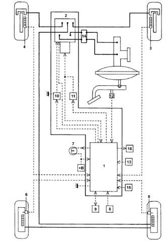
Electrical elements of the system ABS.
1 - electronic control unit ABS,
2 - pressure modulator,
3 - the gauge of frequency of rotation of forward
right wheel,
4 - the gauge of frequency of rotation of forward
left wheel, 5 - Rear Speed Sensor right wheel,
6 - the gauge of frequency of rotation of back
left wheel, 7 - ABS system indicator,
8 - connector for connecting the tester,
9 - the diagnostic socket,
10 - protective relay,
11 - electric pump relay,
12 - the switch of stoplights,
13 - deceleration sensor,
14 - pressure regulator,
15 - all-wheel drive switch,
16 - electronic control unit engine,
17 - full switch drive,
18 - electronic control unit engine.
The engine stalls ...
A very unpleasant problem, which is often enough
meets on models with engine J20A (2,0 l) in the summer
period - the engine periodically stalls during
traffic in road congestion at high temperatures
outdoor air. If the engine stalls, then start
it succeeds only after 10-20 minutes, while the work
The included engine does not cause any complaints,
the readings of the measuring devices are normal,
as well as the levels of technical fluids. The problem is aggravated
also the fact that this malfunction -
"floating" and when diagnosing a car on SRT, as
rule, to identify its cause is not possible. Often, coming to
the solution of the problem "stereotypically", the representatives of SRT
offer to repair the fuel system
(replacement of fuel pump), replace filters, spark plugs,
clean the throttle, etc.
However, the most common cause of this malfunction
- incorrect operation of the distribution sensor
motor shaft caused by overheating
sensor. Because of the incorrect (or temporarily absent)
signal from the distributor
shaft failure of the ignition and injection systems
fuel. In this case, the engine will only start,
when the sensor cools down and starts to function.
Remedy is only possible by replacing
sensor to a new one. It should be noted that in the catalog
spare parts SUZUKI for engine J20A this sensor
is only available as an assembly (catalog number 33100-
65D00) and costs about $ 300, but the same sensor is installed
and the G16A engine for which it is available
separately (catalog number 33220-50G02).
Note: since, most likely, overheating
the camshaft position sensor
due to poor heat transfer in the rear of the motor
compartment, some car owners manage to get rid of
from this problem by removing the metal
black plug (fixed by two
bolts) located in the central part of the motor
under the windshield, thereby
improving heat transfer.
jacj (Friday, 25 August 2023 19:21)
please can i see it